How To Note Flatness Sheet Metal Drawings
Gd T Tips Free State

Quiz Question 8 Geo Tolerances Answers Technical Drawing Engineering Design Geometric Tolerancing

Quiz Question 8 Geo Tolerances Answers Technical Drawing Engineering Design Geometric Tolerancing

Wallet Sized Gd T Symbol Reference Card Omnia Mfg Engineering Symbols Geometric Tolerancing Mechanical Engineering Design

Eliminate Your Fears And Doubts About Mechanical Engineering Drawing Symbols Engineering Symbols Mechanical Engineering Design Mechanical Design

Engineering Drawings Gd T For The Quality Engineer Mechanical Engineering Design Mechanical Engineering Engineering Symbols

A bend table lists propertied of all bends in a flat pattern view of a sheet metal part.
How to note flatness sheet metal drawings.

Gd T Symbols Mechanical Engineering Design Mechanical Design Engineering Symbols

Geometric Tolerances Investment Castings To Precise Geometric Tolerances Milwaukee Precision Geometric Tolerancing Geometric Mechanical Engineering Design
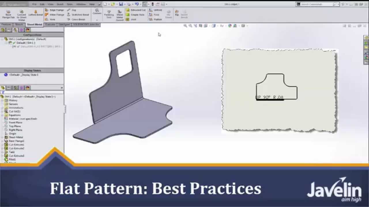
Solidworks Sheet Metal Tutorial Flat Pattern Best Practices Youtube
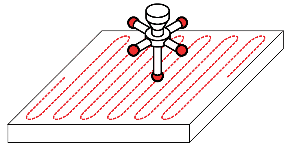
Flatness Gd T Basics
Source : pinterest.com
